|
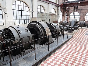
Ward Leonard controlWard Leonard control, also known as the Ward Leonard drive system, was a widely used DC motor speed control system introduced by Harry Ward Leonard in 1891. In the early 1900s, the control system of Ward Leonard was adopted by the U.S. Navy and also used in passenger lifts of large mines. It also provided a solution to a moving sidewalk at the Paris Exposition of 1900, where many others had failed to operate properly.[citation needed] It was applied to railway locomotives used in World War I, and was used in anti-aircraft radars in World War II. Connected to automatic anti-aircraft gun directors, the tracking motion in two dimensions had to be extremely smooth and precise. The MIT Radiation Laboratory selected Ward-Leonard to equip the famous radar SCR-584 in 1942. The Ward Leonard control system was widely used for elevators until thyristor drives became available in the 1980s, because it offered smooth speed control and consistent torque. Many Ward Leonard control systems and variations on them remain in use.[1]
Basic conceptThe key feature of the Ward Leonard control system is the ability to smoothly vary the speed of a DC motor, including reversing it, by controlling the field and hence the output voltage of a DC generator, as well as the field of the motor itself. As the speed of a DC motor is dictated by the supplied voltage, this gives simple speed control. The DC generator could be driven by any means. This 'prime mover' could be an AC motor, or it could be an internal combustion engine (its application to vehicles was patented by H.W. Leonard in 1903[2]). A Ward Leonard drive can be viewed as a high-power amplifier in the multi-kilowatt range, built from rotating electrical machinery. Where the 'prime mover' is electrical, a Ward Leonard drive unit consists of a motor and generator with shafts coupled together. The prime mover, which turns at a constant speed, may be AC or DC powered. The generator is a DC generator, with field windings and armature windings. The input to the amplifier is applied to the field windings, and the higher power output comes from the armature windings. (See Excitation (magnetic)#Amplifier principle for how a generator can act as an amplifier.) The amplifier output is usually connected to a second motor, which moves the load, such as an elevator. With this arrangement, small changes in current applied to the input, and thus the generator field, result in large changes in the output, allowing smooth speed control.[3] A flywheel may be used to reduce voltage fluctuations during sudden load changes. The Ward Leonard system with this modification is known as Ward Leonard Ilgner Control.[4] In that configuration, the synchronous motor, normally used for Ward Leonard control, is replaced by a wound-rotor induction motor. The combination of an induction motor, flywheel, and generator(s) is known as an Ilgner set. It effectively decouples intermittent short-term high loading of the generator from the AC supply.[5][6] A more technical description The speed of a DC motor is controlled by varying the voltage fed to the generator field windings, Vgf, which varies the output voltage of the generator. The varied output voltage will change the voltage of the motor, since they are connected directly through the armature. Consequently, changing the Vgf will control the speed of the motor. The picture on the right shows the Ward Leonard control system, with the Vgf feeding the generator and Vmf feeding the motor.[7] Transfer functionThe first subscripts 'g' and 'm' each represents generator and motor. The superscripts 'f', 'r',and 'a', correspond to field, rotor, and armature.
Eq. 1: The generator field equation Eq. 2: The equation of electrical equilibrium in the armature circuit Eq. 3: Motor torque equation With total impedance, , neglected, the transfer function can be obtained by solving eq 3 . Eq. 4: Transfer function with the constants defined as below: See also
References
|


